In THIS ARTICLE, I will show you some of my experiments and projects with ESP32’s inbuilt sensors — that is, sensors that are already built into your ESP32 board without any additional prerequisites. These inbuilt sensors are:
- Temperature sensor. It has to be noted that this internal temperature sensor doesn’t measure its surroundings; rather, it measures the temperature of the board’s core. Its application is thus limited, although it may be used to create systems such as a sound alarm that goes off if the board is too hot and under a threat of exploding (or more likely, breaking).
- Touch sensor. ESP32 has 10 GPIOs that are capacitive: GPIO 2, 4, 12, 13, 14, 15, 27, 32, and 33. They are able to receive information about small electric variations, such as those caused by the movement of the human skin. This information can be shown in the serial monitor, as I will show you later. If connected to a specialized connectivity pad or even a modified aluminum foil, they can act as a sophisticated input component.
- Hall effect sensor. This sensor detects changes in the magnetic field around the ESP32 board itself. This sensor is located behind the metal lid in the board’s chip. The potential for this magnetic detector is quite exciting: it can do things like calculate proximity and turn doors into an input channel.
Prerequisites
- An ESP32 microcontroller, along with its vertebrate
- A breadboard
- A Micro-USB cord
- A few male-to-male jumper wires
- A fewgreen 3mm LED
- A few 330Ω resistors
- A magnet. I used the incredibly powerful neodymium magnets you often see applied to destroy iPhones in “those” type of videos, but ordinary magnets works just fine.
- Arduino IDE installed for ESP32. I have made a detailed installation guide in my previous article: https://zhillan-arf.medium.com/blink-the-led-with-esp32-5c3f358ea2ff
Investigating the temperature sensor
Other than reading its status on the serial monitor, the use case for this internal sensor is quite limited, as it doesn’t even need any external input. It is mostly set there to prevent our little ESP32 from combusting out of intense heat or something equally catastrophic.
Here, I made it such that the board’s internal LED turns on when the core’s temperature exceeds 50 Celcius (which is quite standard). ESP32 uses Fahrenheit as a default, so we also have to convert it back to Celcius first.
// Show core temperature to serial monitor#ifdef __cplusplus
 extern “C” {
#endifuint8_t temprature_sens_read();#ifdef __cplusplus
 }
#endif#define INTERNAL_LED 2// Variable
uint8_t temprature_sens_read();
int current_temp;// Setup
void setup() {
 Serial.begin(115200);
 pinMode(INTERNAL_LED, OUTPUT);
}// Loop
void loop() {
 Serial.print(“Core temp: “);

 // F → C
 current_temp = (temprature_sens_read() — 32) / 1.8;
 Serial.print(current_temp);
 Serial.println(“ C”);// Internal LED control
 if (current_temp > 50) {
 digitalWrite(INTERNAL_LED, HIGH);
 }
 else {
 digitalWrite(INTERNAL_LED, LOW);
 }

 delay(1000);
}
Here is the result.

Investigating the touch sensor
The input the GPIO receives is stored in the form of an integer. I built a simple circuit to display this by simply connecting the GPIO (we will use GPIO 4) to a jumper cable.
I then set up the code, uploaded it, and observed the changes in the serial monitor by touching the cable’s tip.
// ESP32 Touch Test
// Just test touch pin — Touch0 is T0 which is on GPIO 4.void setup() {
 Serial.begin(115200);
 delay(1000); // Setup time
 Serial.println(“ESP32 Touch Test”);
}void loop() {
 Serial.println(touchRead(4));
 delay(1000);
}
This was the result displayed in the serial monitor. The more I touch the jumper cable with my finger, the lower the number becomes.
As you can see, we can use this reading for more complex circuits. For example, we can set up a threshold to determine whether the cable tip is being touched or not, and thus convert it into a binary form of 1 and 0. For this purpose, I built this circuit:
I then set the threshold of 25 and set up the code.
// Show core temperature to serial monitor#ifdef __cplusplus
 extern “C” {
#endifuint8_t temprature_sens_read();#ifdef __cplusplus
 }
#endif#define INTERNAL_LED 2// Variable
uint8_t temprature_sens_read();
int current_temp;// Setup
void setup() {
 Serial.begin(115200);
 pinMode(INTERNAL_LED, OUTPUT);
}// Loop
void loop() {
 Serial.print(“Core temp: “);

 // F → C
 current_temp = (temprature_sens_read() — 32) / 1.8;
 Serial.print(current_temp);
 Serial.println(“ C”);// Internal LED control
 if (current_temp > 50) {
 digitalWrite(INTERNAL_LED, HIGH);
 }
 else {
 digitalWrite(INTERNAL_LED, LOW);
 }

 delay(1000);
}
This is the result. As you can see, this touch sensor can be used in a similar manner to that of a pushbutton.
Investigating the Hall Effect Sensor
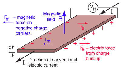
In 1879, Edwin Hall discovered that a voltage difference is created while applying a magnetic field to an electric conductor that carries electric current (and vice versa).
ESP32 can measure the changes in the magnetic field and turn them into a value. The code is quite simple, using hallRead(). Of course, I made sure that the baud of my serial monitor is the same as the one I put in my code.

int val = 0;

void setup() {
  Serial.begin(9600);
}

// put your main code here, to run repeatedly
void loop() {
  // read hall effect sensor value
  val = hallRead();
  // print the results to the serial monitor
  Serial.println(val);
  delay(1000);
}
The numbers on the serial monitor then display the situation of the magnetic field as detected by the internal sensor. This one is for positives,
and this one if for negatives.
Like previously, we can use this information to do some cool stuff. I created this circuit of six LEDs to better visualize the situation of the magnetic field.
For the code, I set 0, 10, and 20 as the threshold for my LEDs, with red representing negative value, blue representing positive value, and a gradient in between. Admittedly, it is quite difficult to position the magnet to what you want, given that electronics and magnets tend to not be of the best of friends.
#define RED 15
#define YELLOW 4
#define WHITE 5
#define GREY 18
#define GREEN 19
#define BLUE 21int val = 0;void setup() {
 Serial.begin(9600);
 pinMode(RED, OUTPUT);
 pinMode(YELLOW, OUTPUT);
 pinMode(WHITE, OUTPUT);
 pinMode(GREY, OUTPUT);
 pinMode(GREEN, OUTPUT);
 pinMode(BLUE, OUTPUT);
}// put your main code here, to run repeatedly
void loop() {
 // read hall effect sensor value
 val = hallRead();
 // print the results to the serial monitor
 Serial.println(val);
 // RED
 if (val < -20) {
 digitalWrite(RED, HIGH);
 }
 else {
 digitalWrite(RED, LOW);
 }// YELLOW
 if (val < -10) {
 digitalWrite(YELLOW, HIGH);
 }
 else {
 digitalWrite(YELLOW, LOW);
 }// WHITE
 if (val < 0) {
 digitalWrite(WHITE, HIGH);
 }
 else {
 digitalWrite(WHITE, LOW);
 }// GREY
 if (val > 0) {
 digitalWrite(GREY, HIGH);
 }
 else {
 digitalWrite(GREY, LOW);
 }// GREEN
 if (val > 10) {
 digitalWrite(GREEN, HIGH);
 }
 else {
 digitalWrite(GREEN, LOW);
 }// BLUE
 if (val > 20) {
 digitalWrite(BLUE, HIGH);
 }
 else {
 digitalWrite(BLUE, LOW);
 }

 delay(200);
}
In fact, rather than displaying information about the field, due to magnetic influence, the serial monitor might occasionally display revelations from the angel Ophanim instead. To reject this apostolic revelation, I simply rebooted the board.

In the end, I managed to position the magnets just right for the camera to see.
In any case, that is all from me this week. Next week(s), there should be a new project far larger, and I will work in a team. Stay tuned, Bye-onara!